ABOUT
THE METER
DESCRIPTION
The Digital Programmable Process meter is a value packed indicator/controller.
Four full digits and broad scaling capability allow for display in virtually
all engineering units. A wide variety of dc current and voltage input
ranges cover typical process applications. Standard features include sensor
excitation and front panel or remote tare. Your meter may be a basic indicator
or it may include analog output or dual relay output. Analog or dual relay
output must be ordered at time of purchase. Analog output is fully scalable
and may be config-ured as a proportional controller, or to follow your
display. Dual 5 amp, form C relays control critical processes. A mechanical
lockout has been included to guard against unauthorized changes.
FEATURES
The following is a
list of standard features:
* 4-digit, 14-segment LED display
* ▒0.03 % accuracy
* 8 dc input ranges: 0-100 mV, ▒50 mV, 0-5 V, 1-5 V, 0-10
V, ▒5 V, 0-20 mA, and 4-20 mA
* 5, 10, 12, or 24 V sensor excitation
* Peak detection and memory
* Front panel and remote tare function
* Non-volatile memory-no battery backup
* 115 or 230 Vac 50/60 Hz power supply
The following is
a list of optional features:
* Dual 5 amp,
form C relay outputs
* Scalable
analog output
* Proportional control
* Easy setup for proportional control
Accessories
and Add-Ons
Table 2-1
Add-On-Options
|
FS
|
Special
Calif/Config. |
|
SPC4
|
NEMA-4
Splash Proof Cover |
|
SPC18
|
NEMA-4
Splash Proof Cover, NEW |
Accessories
|
TP1A
|
Trimplate
panel adapter. Adapts DIN1A/DIN2A cases to larger panel cutouts |
|
RP18
|
19-In.
Rack Panel for one (1) 1/8 DIN instrument |
|
RP28
|
19-In.
Rack Panel for two (2) 1/8 DIN instrument |
|
RP38
|
19-In.
Rack Panel for three (3) 1/8 DIN instrument |
FRONT
OF THE METER
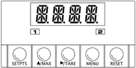
Figure 2-1 shows each part of the front of the meter. |

Figure 2-1. Front-Panel Illustration
|
METER
DISPLAY:
Digital LED display
-1.9.9.9. or 9.9.9.9. 4-digit 14 segment, 0.54" high LED display with
programmable decimal point.
These meter display windows light when appropriate:
1 - Setpoint 1 Status
2 - Setpoint 2 Status
METER BUTTONS
SETPTS BUTTON - In the run mode, this button will sequentially
recall the previous setpoint settings. As necessary, use the  /MAX
and /MAX
and  /TARE
buttons to alter these settings, then press the SETPTS button
to store new values. /TARE
buttons to alter these settings, then press the SETPTS button
to store new values.
Unless you press the SETPTS,  /TARE
, or the /TARE
, or the  /MAX
button within 20 seconds, the meter will scroll to setpoint 2 and then
to the run mode. /MAX
button within 20 seconds, the meter will scroll to setpoint 2 and then
to the run mode.
NOTE: If the dual relay option is not installed or if the L.3=1
on the ôLK.CFö menu, pressing the setpts button will display "v.-03"
which is the meter's software version.
 /MAX Button
In the run mode, this button will recall the PEAK reading since
the last press of the RESET button. /MAX Button
In the run mode, this button will recall the PEAK reading since
the last press of the RESET button.
In the configuration mode, press this button to change the value of
the flashing digit shown on the display and/or toggle between menu choices,
such as "R.1=T" or "R.1=N" on RD.CF menu. When configuring
your setpoint values, press the  /MAX
button to advance the flashing digit's value from 0 to 9 by 1. /MAX
button to advance the flashing digit's value from 0 to 9 by 1.
 /TARE BUTTON
- In the run mode press the /TARE BUTTON
- In the run mode press the  /TARE
button to tare your reading (zeroing) if you configure the Reading Configuration
bit "R.1=T" of the RD.CF menu. If you configure R.1
= N, the /TARE
button to tare your reading (zeroing) if you configure the Reading Configuration
bit "R.1=T" of the RD.CF menu. If you configure R.1
= N, the  /TARE
button has no function. /TARE
button has no function.
In the configuration mode, press the this button to scroll to the next
digit.
MENU BUTTON - In the run mode, press the MENU button
to terminate the current measuring process and enter you into the configuration
mode.
In the configuration mode, press the MENU button to store changes
in the nonvolatile memory and then advance you to the next menu item.
RESET BUTTON - If you hard reset (press the MENU button
followed by the RESET button) or power off/on the meter, it shows
"RST", followed by "PROC".
In the run mode, press the RESET button to reset tare, if any.
The meter shows "T.RST" and returns to the run mode.
In the configuration mode, press the RESET button once to review
the previous menu. Press the RESET button twice to perform a
hard reset and return to the run mode.
In the peak mode, press the RESET button to reset peak values.
The meter shows "PK.RS" and returns to the run mode.
In the setpoint mode, press the RESET button to reset the latched
setpoint. The meter shows "SP.RS" and enters the run mode.
When in setpoint or configuration mode, if the meter shows 9999 or -1999
with all flashing digits, the value has overflowed. Press the  /MAX
button to start a new value. /MAX
button to start a new value.
BACK OF THE METER
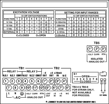
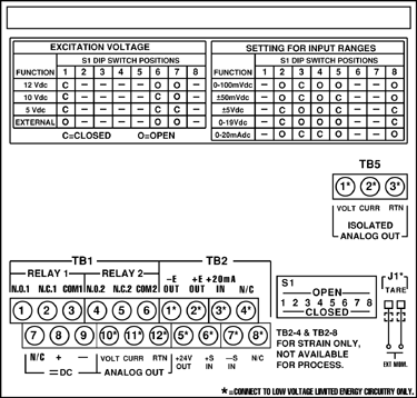
Figure 2-2 shows the label describing the connectors on the back of
the meter. Table 2-2 on the following page gives a brief description
of each connector at the back of the meter.

Figure 2-2. Connectors (AC-Powered)

Figure 2-3. Connectors (DC-Powered)
Rear
Connector Description Table 2-2
|
CONNECTOR
|
DESCRIPTION |
|
TB1-1
|
Setpoint 1: Normally open (N.O.1) connection |
|
TB1-2
|
Setpoint 1: Normally closed (N.C.1) connection |
|
TB1-3
|
Setpoint
1: Common 1 (COM1) connection |
|
TB1-4
|
Setpoint
2: Normally open (N.O.2) connection |
|
TB1-5
|
Setpoint
2: Normally closed (N.C.2) connection |
|
TB1-6
|
Setpoint
2: Common 2 (COM2) connection |
|
TB1-7
|
AC
Line connection (no connection on DC powered units) |
|
TB1-8
|
AC
Neutral connection (+ Input on DC powered units) |
|
TB1-9
|
AC
earth ground (DC- power return on DC powered units) |
|
TB1-10
|
Analog
voltage output |
|
TB1-11
|
Analog
current output |
|
TB1-12
|
Analog
Return |
|
TB2-1
|
-E:
Negative excitation connection to/from meter (5, 10, 12 V) |
|
TB2-2
|
+E:
Positive excitation connection to/from meter (5, 10, 12 V) |
|
TB2-3
|
+20
mA connection for analog input |
|
TB2-4
|
Not used. |
|
TB2-5
|
+24 V output connection |
|
TB2-6
|
+S
Positive signal input |
|
TB2-7
|
-S:
Negative signal input and return for +20 mA or +24 V |
|
TB2-8
|
Not
used |
|
TB5-1
|
Isolated
Analog Voltage Output |
|
TB5-2
|
Isolated
Analog Current Output |
|
TB5-3
|
Isolated
Analog Output Return |
|
J1(1-2)
|
Remote
tare connection with a momentary switch |
The DIP switches are
located at the S1 position at the back of the meter (Refer to Figure 2-2).
Use a small instrument such as a paper clip to change the switches from
open to closed. Table 2-3 lists DIP switch settings at the S1 position
required to complete the setup of your meter.
DIP
Switch Positions/Input Range & Excitation Voltage Settings
Table 2-3
|
FUNCTION
|
S1
DIP SWITCH POSITIONS
|
|
C=
Closed / O= Open
|
1
|
2
|
3
|
4
|
5
|
6
|
7
|
8
|
|
SETTINGS
FOR EXCITATION VOLTAGE
|
|
Internal
5/10/12 excitation
|
C
|
-
|
-
|
-
|
-
|
-
|
-
|
-
|
|
External
5/10/12 excitation
|
O
|
-
|
-
|
-
|
-
|
-
|
-
|
-
|
|
Internal
12 V excitation
|
C
|
-
|
-
|
-
|
-
|
O
|
O
|
-
|
| Internal
10 V excitation
|
C
|
-
|
-
|
-
|
-
|
C
|
O
|
-
|
|
Internal
5 V excitation
|
C
|
-
|
-
|
-
|
-
|
C
|
C
|
-
|
|
SETTINGS
FOR INPUT RANGES
|
| 0-100
mV dc |
-
|
O
|
C
|
O
|
O
|
-
|
-
|
O
|
|
▒50
mV dc
|
-
|
O
|
C
|
O
|
C
|
-
|
-
|
O
|
|
▒5
V dc
|
-
|
C
|
O
|
O
|
C
|
-
|
-
|
C
|
|
0-10
V dc
|
-
|
C
|
O
|
O
|
O
|
-
|
-
|
C
|
|
0-20
mA dc
|
-
|
O
|
C
|
C
|
O
|
-
|
-
|
O
|
Disassembly
You may need to open up the meter for one of the following reasons:
* To check or change the 115 or 230 Vac power jumpers.
* To install or remove jumpers on the main board.
Note: Disconnect the power supply before proceeding.
To remove and access the main board, follow these steps:
1. Disconnect main power from the meter.
2. Remove the rear case cover.
3. Lift the back of the main board upwards and slide it out of
the case.
|